Hello, the term "AVAGO High Line" you mentioned is a common industry terminology, typically referring to specific fiber optic models produced by AVAGO High or Broad-com after its subsequent merger with Broad-com. The increased attenuation of such fibers is a comprehensive issue that requires systematic investigation and resolution.
The root causes of signal attenuation primarily stem from the optical fiber's inherent quality, installation techniques, and external environmental factors. Below are detailed improvement steps and solutions:
Step 1: Precise Diagnosis and Localization (Identify the Attenuation Point)
Before blind treatment, the location and cause of attenuation must be determined first.
1. Use OTDR testing:
· An OTDR must be used instead of a basic optical power meter. The OTDR generates a 'curve chart' of the fiber, clearly showing the loss at each point along the entire fiber link.
· Analyze the OTDR curve:
· Welding point spike: If a welding point shows abnormally high loss (e.g.,>0.1 dB), it indicates poor welding quality at that location.
· Steep drop: The curve experiences a sudden decline, followed by partial recovery or sustained high loss, typically caused by macro or micro bending.
· End reflection peak: Check if the reflection peak at the link end is clear and if the loss value falls within the acceptable range.
2. Identify high-loss points:
· Connectors/adapters: Clean all fiber optic connector end faces (using dedicated cleaning brushes and microscopic inspection). Poor-quality or dirty connectors are common sources of attenuation.
· Welding joint: Locate the welding joint with abnormal wear.
· Bend points: Inspect all fiber optic distribution frames and junction boxes to ensure corners have sufficient curvature radius (typically>30mm).
Step 2: Targeted Improvement Measures
According to the diagnostic results, corresponding measures should be taken.
A. Improve the welding quality (due to high loss at the welding joint)
1. Optimize the welding process:
· Welding machine calibration: Perform periodic discharge calibration to ensure parameters (discharge intensity, duration) match the fiber type (e.g., G.652D).
· Clean cutting blades: Use high-quality cutting blades (e.g., Sumitomo, Furukawa) to ensure smooth and burr-free end surfaces. Clean the blade surface before each cut.
· Clean fiber: Thoroughly clean the fiber coating with anhydrous alcohol and specialized wiping paper prior to splicing.
· Environmental control: Avoid outdoor welding in windy, sandy, or humid environments. Use tents or protective covers.
B. Eliminating bending losses (for macro/bending/micro bending)
1. Ensure minimum bending radius:
· Static installation: The bending radius should generally be at least 10 times the fiber diameter (for example, a 2mm outer diameter cable requires a radius of ≥20mm, though ≥30mm is strongly recommended).
· Dynamic installation (e.g., frequent movement): not less than 20 times the diameter.
· Inspect all connection points: cable trays, bends, and cable penetrations in the distribution frame.
2. Use high-quality fiber optic cable trays and accessories:
· Replace the old fiber optic tray with its cramped interior and sharp edges.
· Ensure the optical fiber is naturally and smoothly coiled without compression or twisting.
C. Optimizing connections and end-face processing
1. Clean the end face thoroughly:
· Clean all jumper leads, adapters, and device interfaces with a two-step method (blow dry first, then wipe).
· A surface inspection microscope (200x or 400x) must be used to check for scratches and stains.
2. Replace the inferior connector:
· If you notice irreparable scratches on the connector's end face or poor connector accuracy (e.g., mismatched UPC/APC models), immediately replace it with a reliable brand jumper.
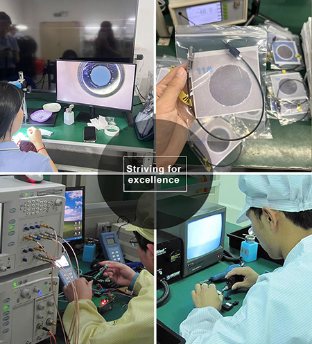
3. Use grinding equipment to grind both ends of the AVAGO high-voltage cable, and inspect the ground end faces under a microscope to verify compliance with requirements, followed by attenuation testing.
D. Inspect the optical cable itself and its external environment
1. Physical examination for injury:
· Inspect the optical cable for flattening, excessive stretching, or sharp cuts, particularly at manholes and pipeline entrances.
2. Environmental stress:
· When optical cables are deployed in environments with significant temperature variations or frequent vibrations, prolonged stress can lead to increased micro-bend loss. Consider adding protective sleeves or re-routing the cables.
3. Hydrogen loss effect (for aging optical fibers or special environments):
· In specific chemical environments or metal-clad optical cables, hydrogen molecules can penetrate the glass, leading to increased signal attenuation. This necessitates the replacement with hydrogen-resistant optical fibers or metal-free cables.
Step 3: Systematic Prevention and Management
1. Documenting:
· Record the OTDR test curve, fusion point location, loss value, and cleaning records for each measurement. Establish baseline data for future comparison.
2. Standardized work processes:
· Develop and rigorously enforce Standard Operating Procedures (SOPs) for fiber optic installation, splicing, and cleaning, while providing training to construction personnel.
3. Quality control of spare parts:
· Procure reputable brands of optical fibers, patch cords, connectors, and protective sleeves.
4. Periodic maintenance:
· Make OTDR testing and fiber optic link cleaning part of routine maintenance, not just a stopgap fix when issues arise.
Summary of process improvement list
1. Measurement: Locate high attenuation points using OTDR.
2. Inspection: Examine all end faces under a microscope.
3. Clean: Thoroughly clean all connection points.
4. Check: Verify that the radius of all bends is adequate.
5. Replacement: Replace inferior jumpers and damaged protective sleeves, and rework high-loss solder joints.
6. Prevention: Standardize construction, perform regular maintenance, and establish records.
Final critical note: If the attenuation remains significantly higher than theoretical values (e.g., G.652D fiber>0.4 dB/km at 1310nm,>0.25 dB/km at 1550nm) after completing all procedures, and the attenuation is uniformly distributed across the entire fiber length, this is likely due to fiber aging during manufacturing or prolonged use. In such cases, the most effective solution is to replace the entire fiber optic cable.
We recommend starting with basic cleaning and inspecting bends, which typically resolves over 50% of on-site attenuation issues.